This one was an easy direction from the beginning - make the
car look somewhat original, but have the car handle nothing
like the original car. If you have not experienced it for yourself, try
taking a 60's car out for a drive. They are great in a
straight line, but put them up against a corner and you lose.
Any car of today will drive circles around these classics.
The original plan for the project was to just run a few bolt on
aftermarket parts, lower the front upper control arm points and
see what that did. Two problems here - no matter what you
bolt on, you are still using the same suspension points.
Second problem - the parts are very expensive for what you get
out of them, and you pretty much have to buy them new.
Finally, when you bolt all this and and all is said and done,
these parts were not really designed to work with one another
from the beginning as a package - they are only designed that
way because most enthusiasts are not fabricators, nor do they
want to cut up an original car.
The more we got into things, the more extreme things seemed to
get. First it was just a brake modification, then it
progressed to a couple more parts here and there, and now we are
looking at a complete suspension, brake and steering replacement front and rear.
As you can see, we got a little carried away on this one. Follow the links above to see what was done with each chassis system.
Chassis Jig Design and Fabrication
All the talk about custom suspension sounds great on paper, until
you actually think about what it involves. Clearly all of the
parts from a 2004 Mustang were not designed to bolt up to 1968 Torino.
This leads to several questions. On of the most frequently asked
questions we get is how do you know where to put
everything? How can you ensure everything is set up the same
from left to right, front to back and vertically? How can you build a second car faster (in
our case). It would also be helpful if it could somehow be
referenced to known published data from a Mustang.
The problem is, if you located one critical component incorrectly,
everything else that goes on after that will be off, and will be very
difficult to fix. A small amount of time invested here will be
well worth the effort.
Enter the chassis jig. If a garage floor was
perfectly flat - this would be a great measurement reference.
Unfortunately, most are not flat as they are sloped for drainage.
Besides that, a floor is definitely not portable. The other problem is that
is difficult to bolt, clamp or weld fixtures to the floor. There
is also little to no repeatability if you switch locations of the
build, plus it is easier to work on the vehicle when you can access
it from below.
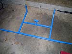
Rather than spend thousands of dollars to buy a commercially
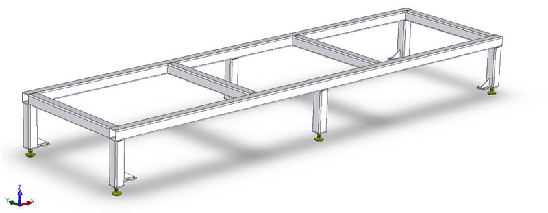
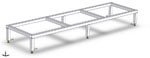
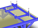
available unit, we decided to do some research and build our own. As you can see
below, first a concept was drawn up in Solidworks to get an idea of
what it would and should look like. After going through a dozen
ideas and revisions, the following is the final design. The
objective of this is to build a portable chassis fixture that is
perfectly flat (easier said than done as we found out) and could be
leveled on any floor surface using adjustable feet. The
structure needs to be simple enough that it is easy to work around,
but at the same time has enough bracing that it is stiff enough to
resist deflection once a complete vehicle is set on it. This may
not be the most practical thing to do for someone who is only going
to build one car, but for us, there will be many cars built over
time.
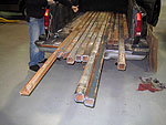
The next part of the process involved getting materials etc.
The main structure is built out of 3"x3"x1/4" steel,
and the cross bracing
is made from 2"x2"x3/16" steel. The adjustable feet were
purchased at a local industrial supply store. The legs are made
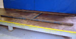
by Carr-Lane and are part number CL-8-SLF. Turns out we found the steel through
a wanted ad we placed locally on Craigslist. The steel was from a local
billboard that was torn down and being sold for scrap. The price
was right, so we drove away with a truck loaded with steel (the truck
seemed to sag nicely after this). The steel was not the nicest
looking as it was covered in rust, but that is nothing a little paint
can't fix as you can see. The following is a cost
breakdown for the basic shell of the chassis jig:
~100ft 3"x3"x1/4" steel: $100 (Leftover steel will
likely be sold to recover some cost)
2"x2"x3/16" steel: Found in
scrap bin
Leveling feet for base of legs & nuts for legs: $70
Paint and misc shop supplies: $35
Total cost: $205
Labor: No charge :)
Fortunately, we had access to a commercial surface plate as a
starting point to ensure flatness of the top surface. A
straightedge was also used to ensure the part was flat during the
process.
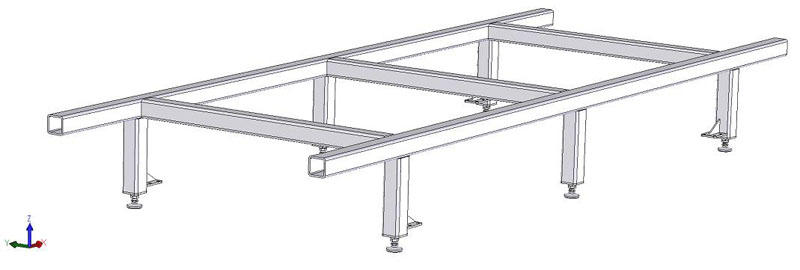
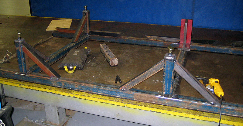
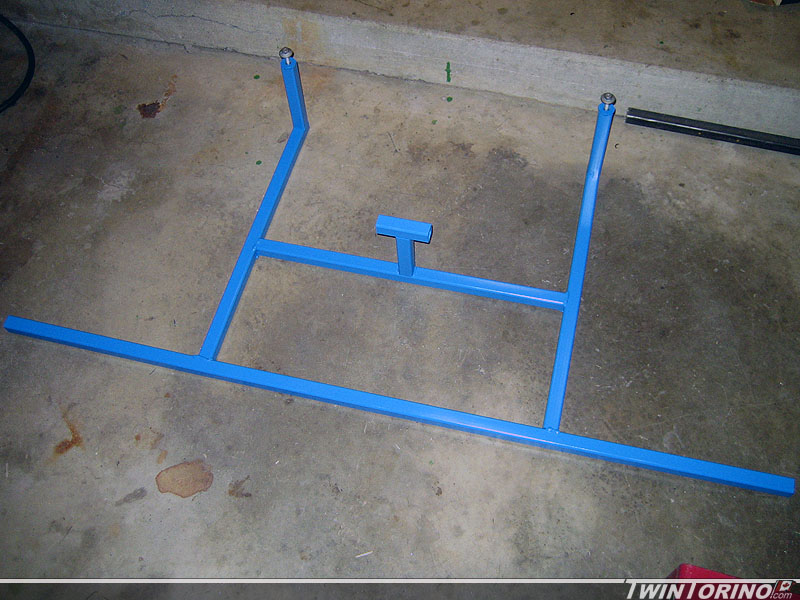
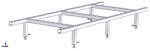
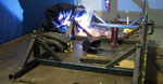
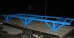
As you can see below, the jig is not very complicated, and is
basically made up of simple rectangular beams cut at 90� or at an
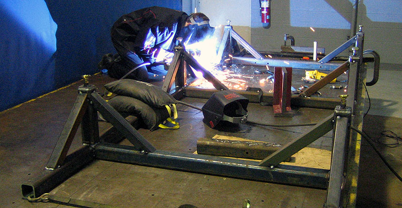
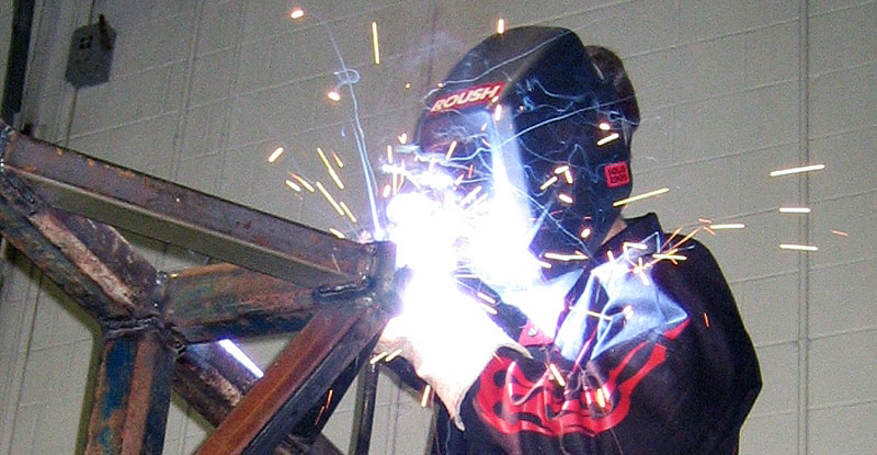
angle in the case of the braces. We opted to MIG these parts
together as it is a lot faster and puts less heat into the parts
(with the exception of the base of the legs where TIG was used).
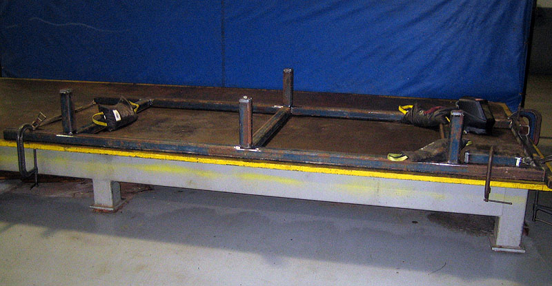
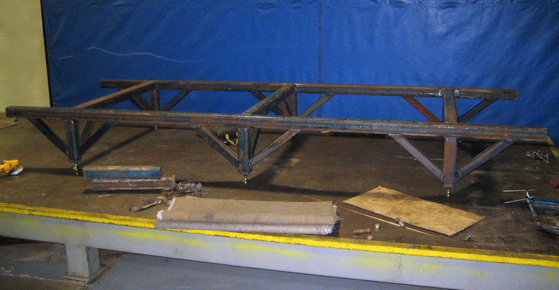
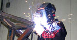
Seems simple enough.. however once you weld these pieces together,
there is a considerable amount of movement of the pieces
(considerable being measured in mm), and once
the jig was unclamped from the surface, the residual stresses in the
parts caused some of the ends to lift. Since this meant the
top surface is no longer flat, this is a big issue. Time spent
here to make the jig as flat as possible is well worth it. This proved to be the
most tedious part of the build, where we had to cut some of the
welds, apply heat to joint, and then re-weld. This was done
over and over again until the jig was perfectly flat on its own
using 12' straightedges. Once finished, the jig was coasted in
Miller Blue of course :).


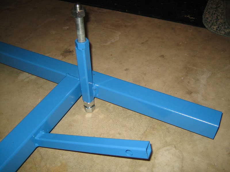
Chassis Jig Add-ons:
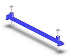
Body Cradles
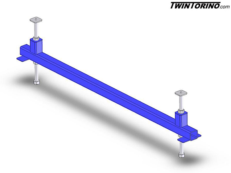
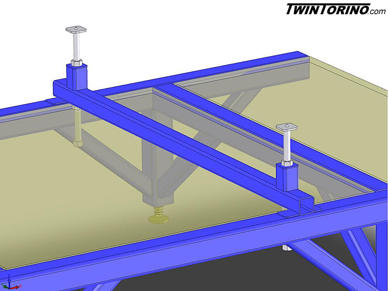
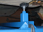
The first and most obvious addition to the chassis jig
are the body cradles. The allow the body to be clamped to the
chassis jig, and also allow the body to be raised and lowered relative
to the top face of the plate. The reason for this becomes more
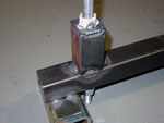
obvious after looking at the suspension cradles. There are two
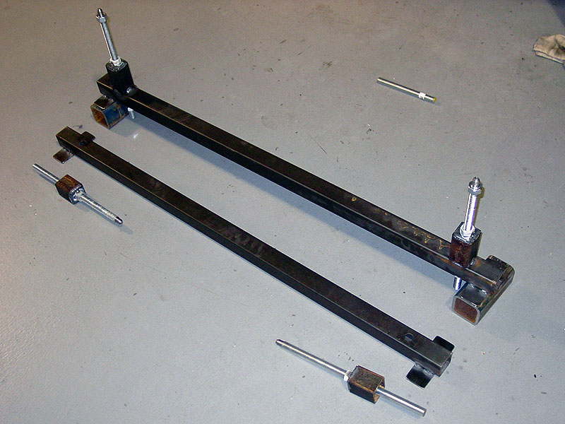
similar body cradles, one front, and one rear. Each cradle has
two screw jacks which allow the vehicle to be positioned precisely
up and down. These were made using 3/4" threaded rod and
nuts from Home
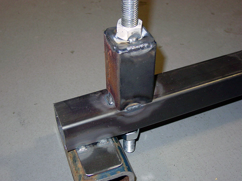
Depot. The rest of the cradles are made of 2x2x1/8 steel which
was welded together using a TIG welder (just cause). One of the nuts is welded to the base, one to the
adjuster rod, and a third is used as a jam nut. With this
design, the car can be raised and lowered from below with an impact
wrench. We decided to use a plate that will be welded to the
torque boxes of the car and will act similar to a dowel pin for
locating the vehicle, which can be seen below.
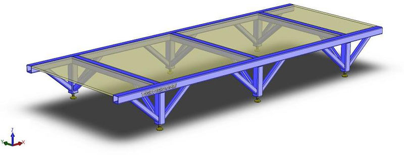
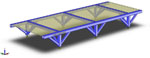
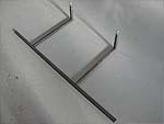
Plywood Measurement Surface
As noted below, one of the goals in building the
chassis jig is to make it perfectly flat, both in construction, and
when it is set up underneath the vehicle (using the adjusters).
This is done so you can now put gravity to use. The inside
portions of the jig were made to be 48"x48" so a std plywood sheet
could be put in between (aside from it being ideal outer dimensions to
boot). The sheet of plywood can now be used to mark on for
measurements, centerlines, etc. A simple plumb bob is used to
determine locations both laterally (cross car) and longitudinally
(lengthwise). The heights can now be determined using height
gauges and steel rules using the flat base across the jig as
reference.
Suspension Cradles
When you first start a project like this, you don't
really know where the suspension needs to go at first. You
have a rough idea of where the body needs to go, but that is it.
Before the actual mounting components can be fabricated, the
suspension and body will be mounted independently to the chassis
jig. There is one cradle for the front suspension/engine, and
another for the rear IRS. Both
the front and rear suspension will be placed at "as designed position"
which provides for optimal suspension dynamics. Unlike a
lowered SN95 Mustang which causes the vehicle to ride up the
camber/toe curves, our vehicles will be lowered, but behave as
though there were designed in that position. We will not
have to worry about things like bump steer as a "modified
lowered" Mustang would. This may mean we will have to cut
holes in the trunk floor to clear the IRS, but it is worth it
for the performance advantages.
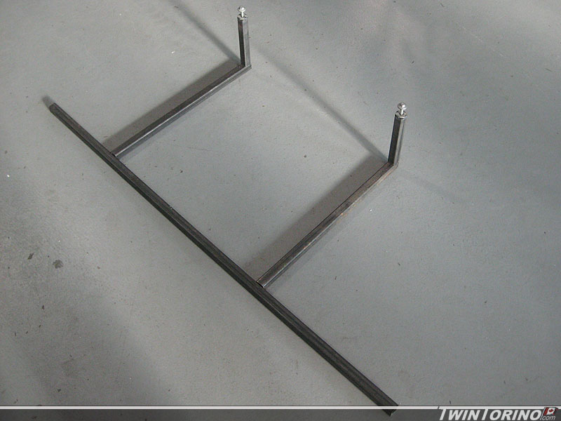
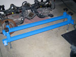
Front Suspension/Engine Cradle
In order to get the suspension in place and get it to the right height, we needed to build a fixture that would work with our chassis jig. The k-member was used as reference and mounting points were chosen and located. Once this was built, it was placed on the vehicle so a tire and wheel could now be put into place.
  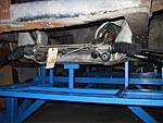
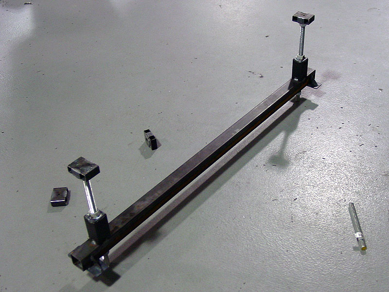
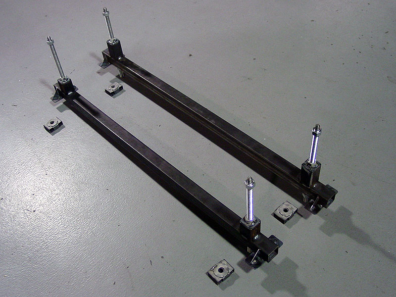
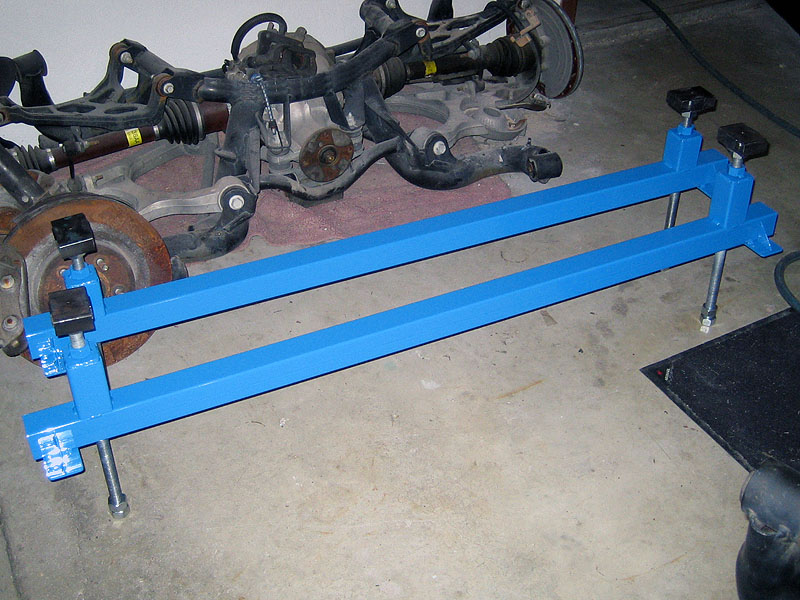
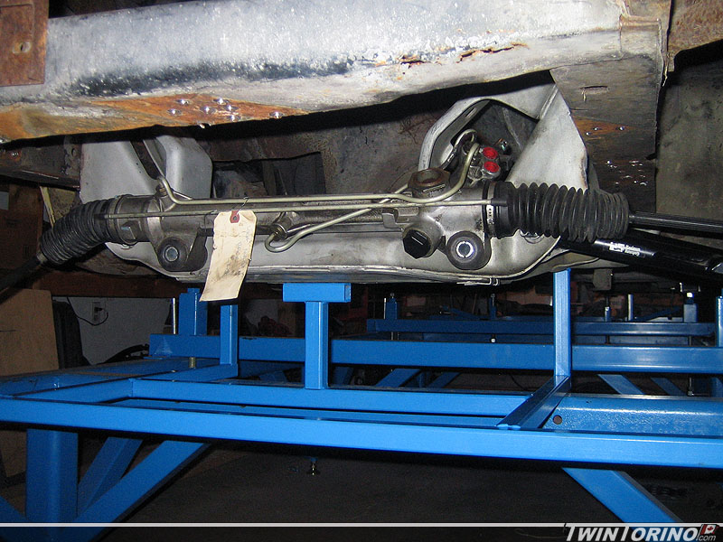
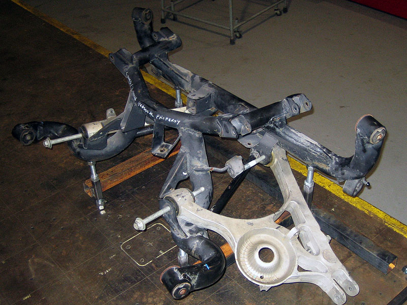
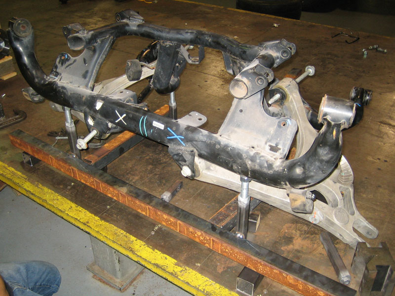
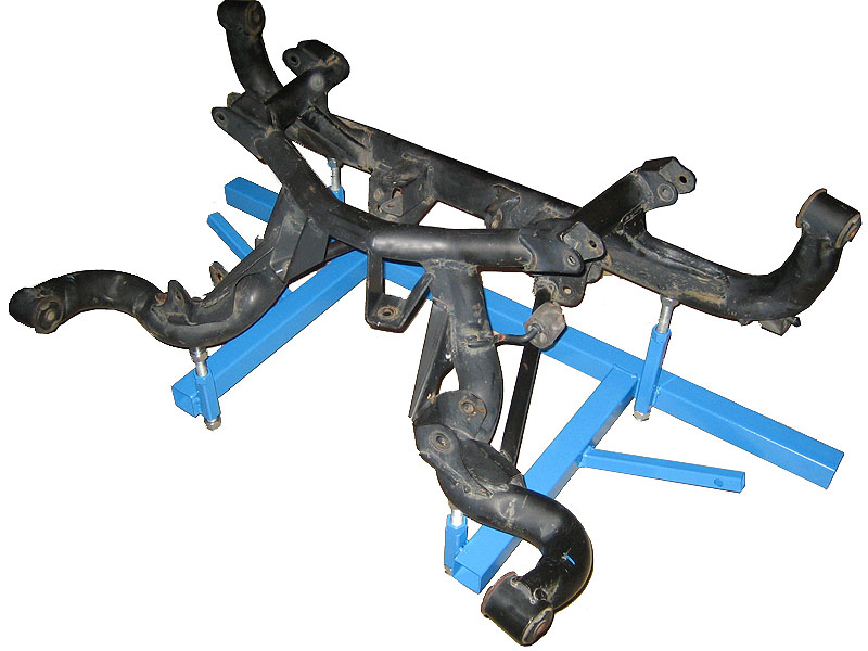
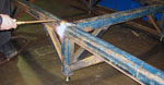
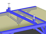
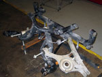
Rear IRS Cradle
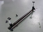
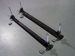
The cradle for the IRS is shown below. This piece
clamps to the chassis jig, and allows for height adjustment/pitch of the
IRS assembly. The cradle picks up on 4 existing holes in the
IRS, which will make this a valuable tool for any IRS installation
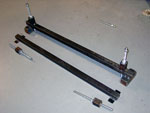
from now on. Thankfully we had and extra IRS cradle and control
arms for the build to make the parts easier to work with. The
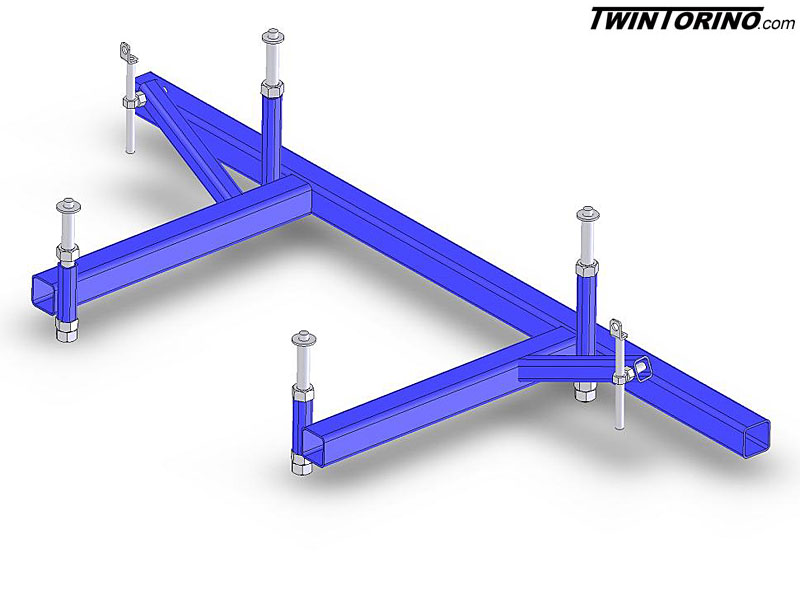
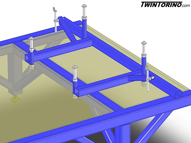
design was first made up using Solidworks to figure out the
lengths etc, then was physically built as shown. The
fixture also allows the height of the control arm to be adjusted
to set the wheels at the correct ride height.
Solidworks conceptual CAD design with and without chassis jig in
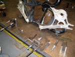
place

Fabrication of actual fixture using mocked up decontented IRS

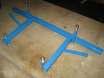
Final completed fixture (missing control arm height adjusters)


|