|
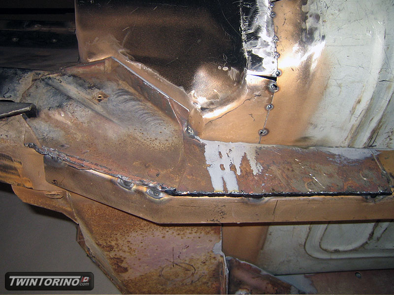
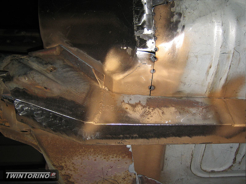
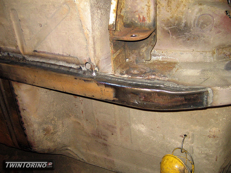
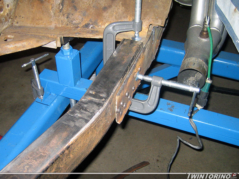
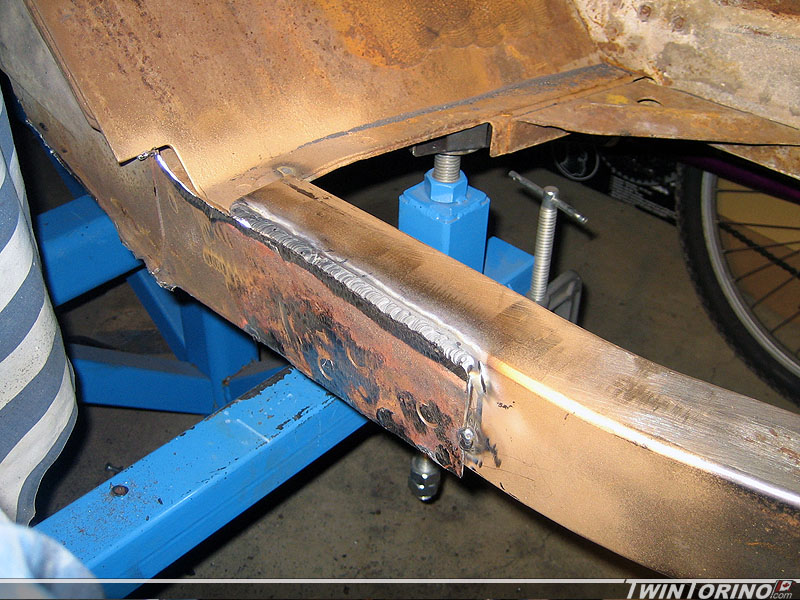
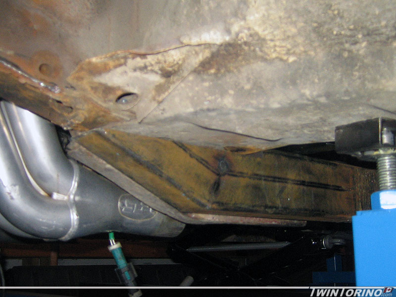
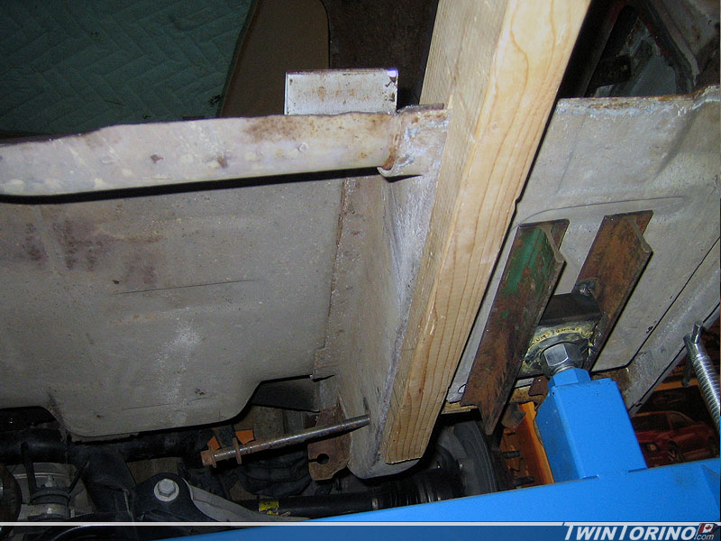
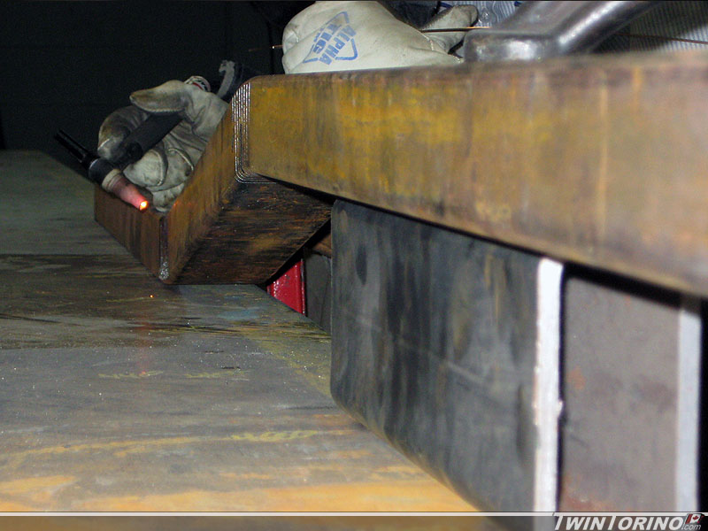
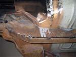
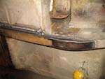
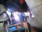
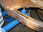
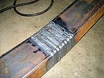
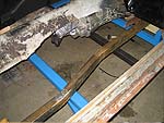
3/28/11 - Finished welded the front of the subframe connector to the old transmission brace.
 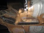
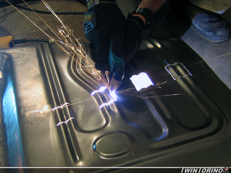
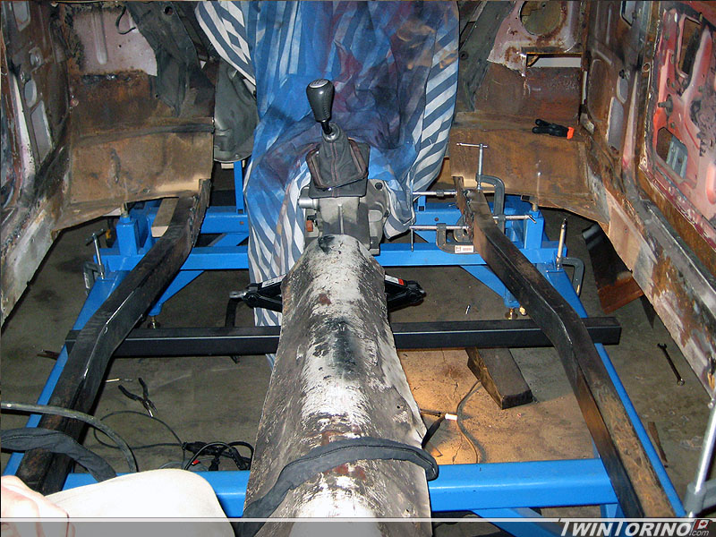
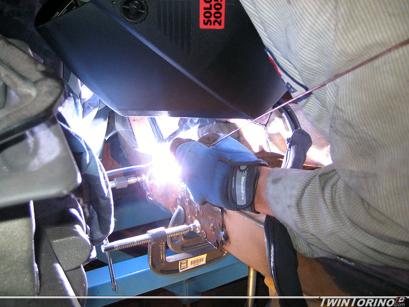
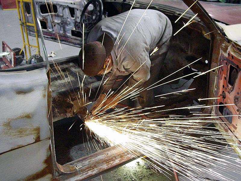
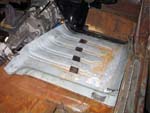
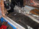
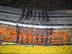
3/22/11 - Got the body up on the rotisserie and started welding the underbody. There are many hours of welding ahead. A combination of MIG and TIG will be used depending on material thickness and metal conditions.
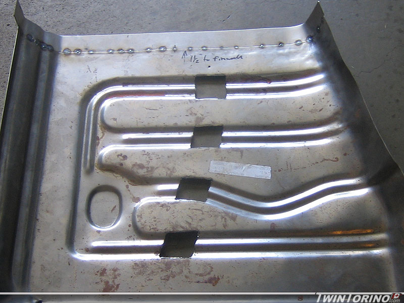
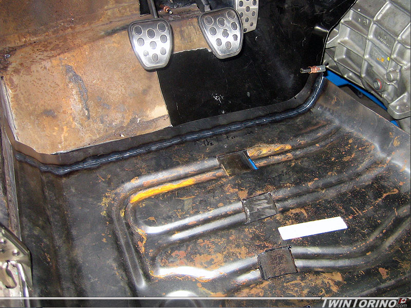
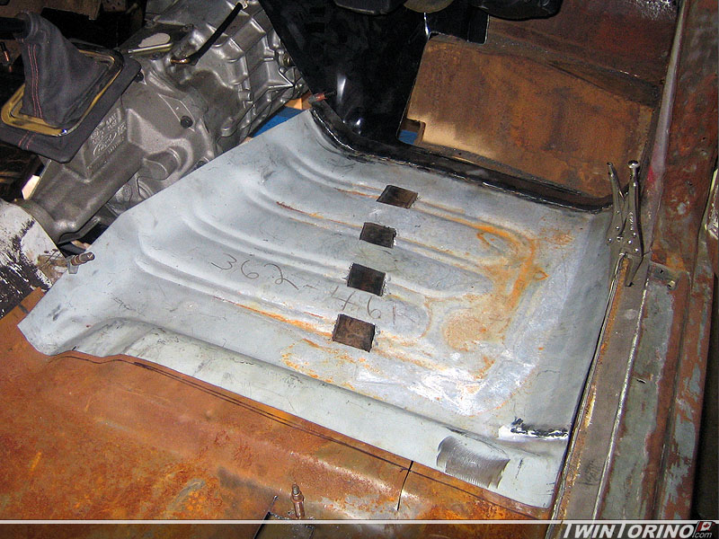
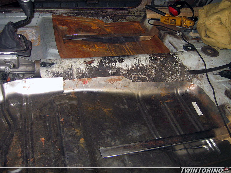
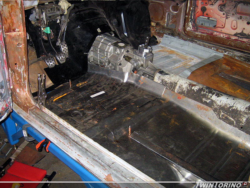
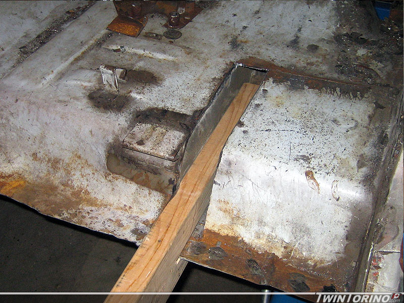
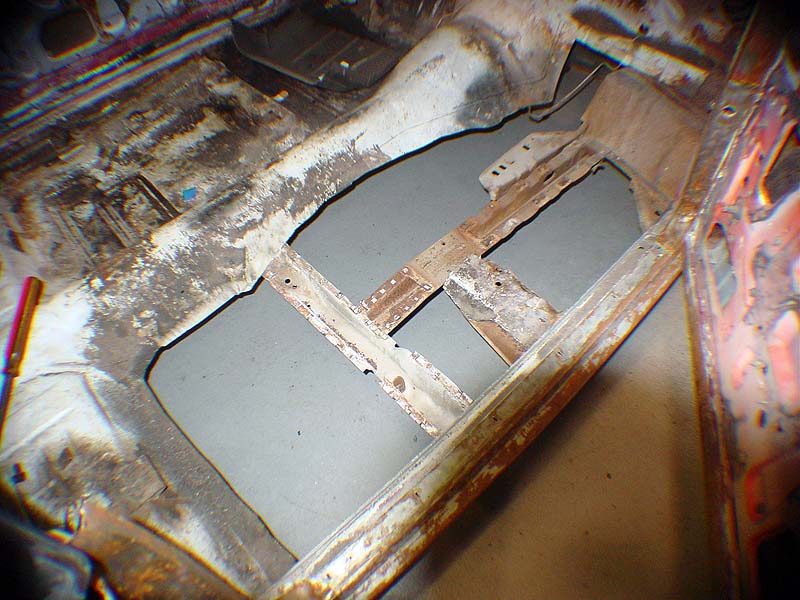
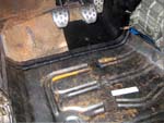
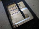
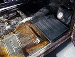
6/22/09 - Put the cutouts in the pass side floors to mate up with the subframe connectors, and added and inch and a half to the front of each panel to meet up with the Mustang firewall. That way I no longer need to use Torino toe pans (unfortunately I bought them already). With the way the subframe connectors are set up in the car, the floors are lowered approx 3/4 in the front to get a bit more room up front for the pedals etc. I quickly put in the seats and dash and it feels perfect for driving.. can't wait. Now onto the firewall and trans tunnel.
5/27/09 - Now back to the interior once again. The top portions of the subframe connectors are now completely welded in, so it is time to finish up the firewall and the floors. The firewall was trimmed to fit around the torque box and was adjusted to the final position both side to side and up and down. The floor needed to be slotted to clear the subframe connectors both front and back. We ended up lowering the floor 3/4" to get everything where we wanted it. Just need to add an inch or two to the front pan so it will mate up with the firewall. This works out great and will no longer require toe pans. I had to pull out the hammer and dolly set to get the profile of the front of the floor pan to match the firewall - worked out quite well in the end.
Just need to make up extensions for both sides of the firewall and make up a tranmission hump, then everything can be welded in for good.
4/28/09
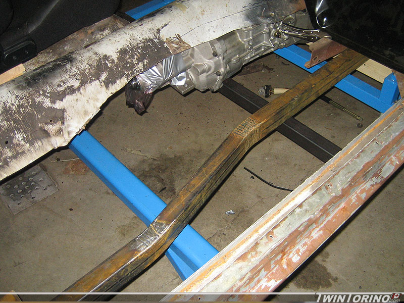
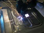
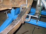
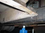
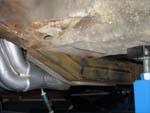
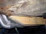
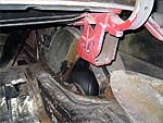
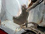
- Got the subframe connectors clamped in and tacked into position. Coated everything with SEM copper weld through primer and started welding them in for good. Don't think they are are going anywhere now. The old transmission crossmember worked out perfect to stiffen these up and tie them into the subframe.
4/7/09 -
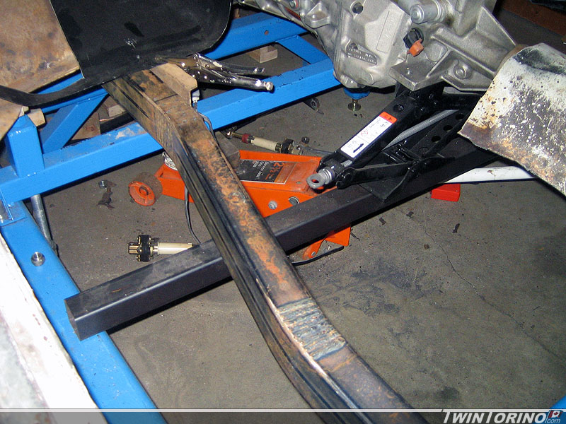
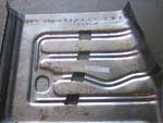
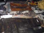
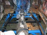
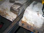
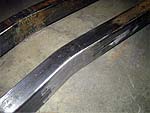
Subframe connectors are now ready to weld in (finally). Just need to prep all the areas for welding now. Very happy with how they fit. There is lots of weld area to tie these into the existing front and rear subframes. Should increase the stiffness of the chassis quite a bit.
If all goes well.. they should look they are supposed to be there. Also need to rework the brace that used to hold the trans crossmember so it sits flush with the subframe connector.
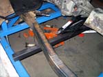 
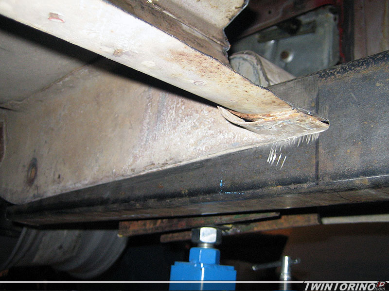
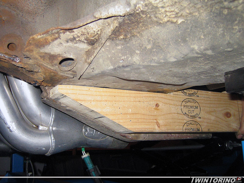
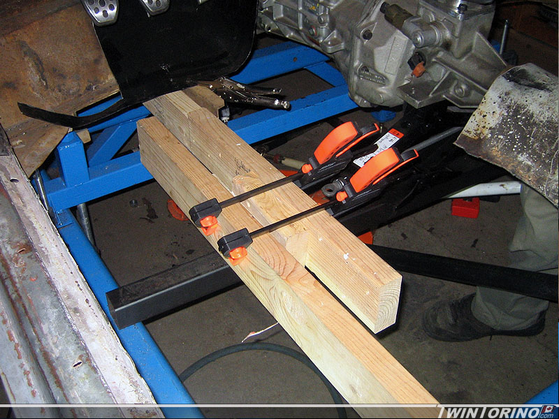
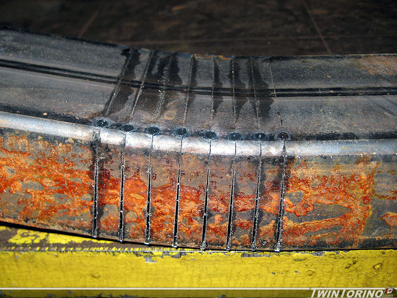
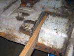
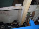
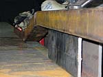
3/25/09 - It was finally time to cut out the drivers side floor section to make room for subframe connectors and the new floors. Have the subframe connectors all figured out now. Used some 2x4's to determine the overall diemsions and how to cut the steel. Came out quite nicely. Pictures can do the talking on these. As you can see - they tie directly into the rear frame rails (requiring cutting into the framerail area from above) and will also tie into the front frame rails. When all is said and done - they should look somewhat natural. Next comes cutting the actual connectors to shape and welding them in. To do this, a bandsaw was desirable so we ended up finding a broken one locally for $25 (wood/metal) so that should be up and running in the next couple of days.

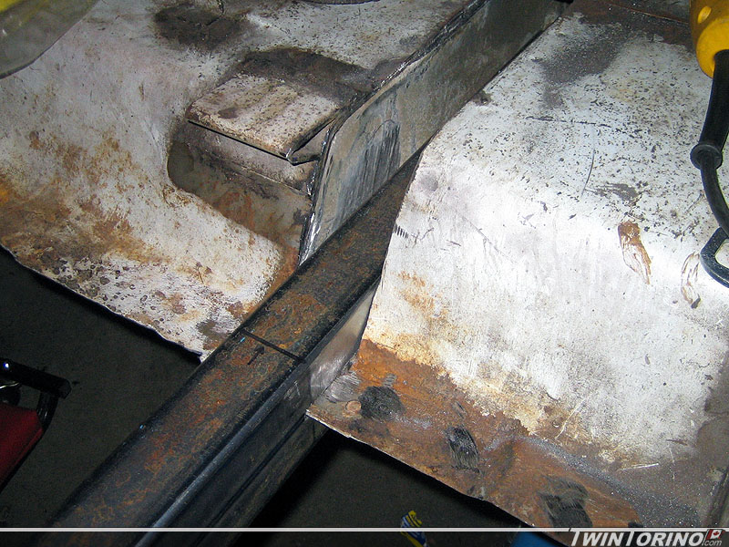
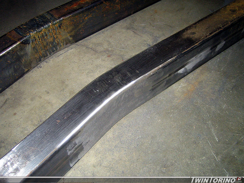
3/6/09 - Subframe connector fabrication continues. Finished welding up the connectors, and moved on to cleaning up the welds. Hard to even tell they were welded now. Now looks like a nice smooth mandrel bend.
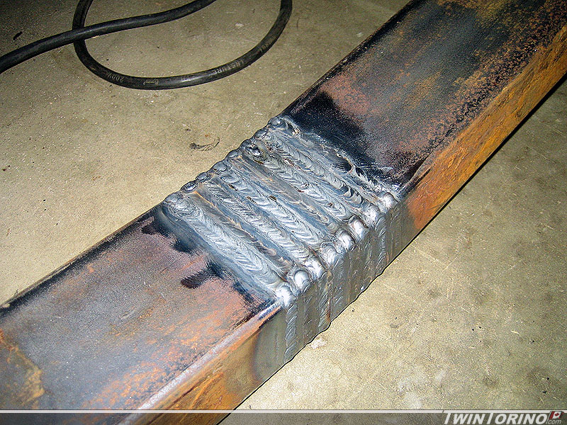
2/23/09 - Subframe Connector Time: Finally making some progress on stiffening up the chassis. Since the floors are cut out, we decided to run a full connector from the front torque box / frame rail to the rear one. The goal here is to make it look like the frames connect to one another and make it appear factory installed. First problem with that idea is the front subframe is offset 4" from the rear. We decided to add a 4" jog into the part as shown below. This involves calculating the angle to bend the material, measuring the width of the bandsaw blade, and then making the necessary cuts to get there. It is a rather long process in comparison to just notching it out, but looks much cleaner (even though noone will likely notice once installed). Hard to explain what we are doing to connect them to the front or rear, so you'll have to wait for pictures in the next couple of weeks :).

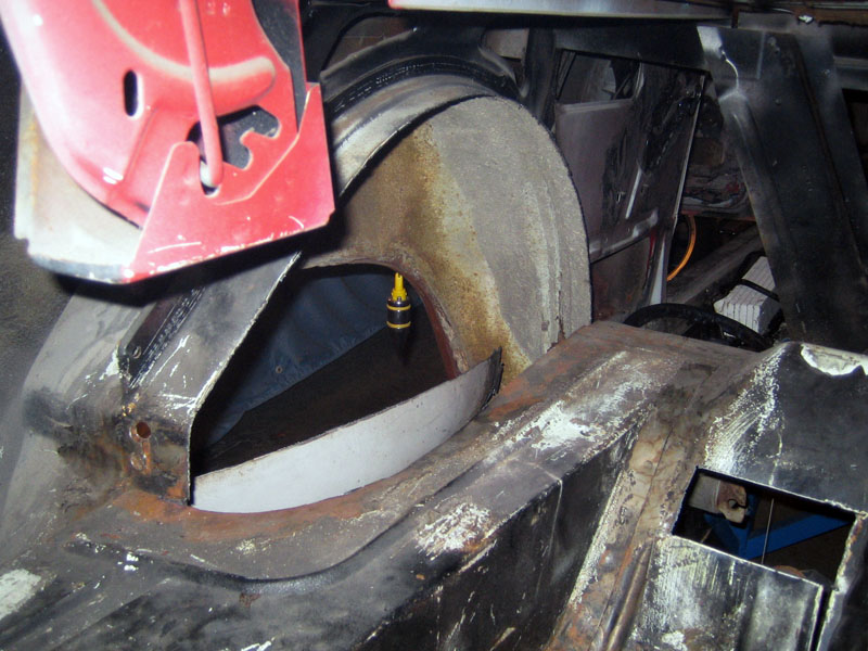
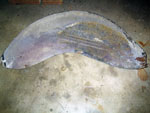
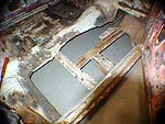
12/20/08 - Minitub Part 2:
Took the time to cut out the other side to complete things as far as tub removal goes. The next step is to add material into the tubs and the modify the frame rails to make room for the wider wheels.
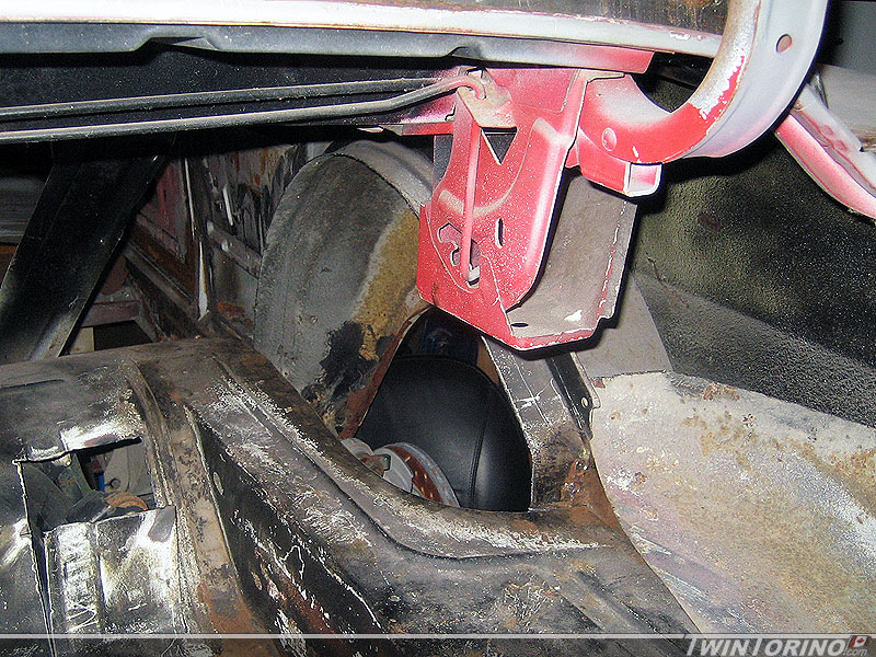
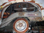
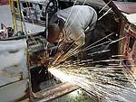
12/11/08 - Minitub Time:
Finally time to make some progress on the body. Since the 315 or 335 tires will not clear the inner wheel wells, this means we need to make more room. The suspension will also move differently than a solid axle (you get camber changenow with the IRS), so that further defines the need to minitub the rear of the car. Since there is no kit available - we need to do this ourselves. Plasma cutter is worth its weight on gold during this step. More details to follow as we progress. 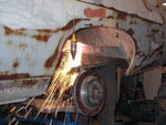 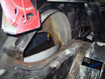
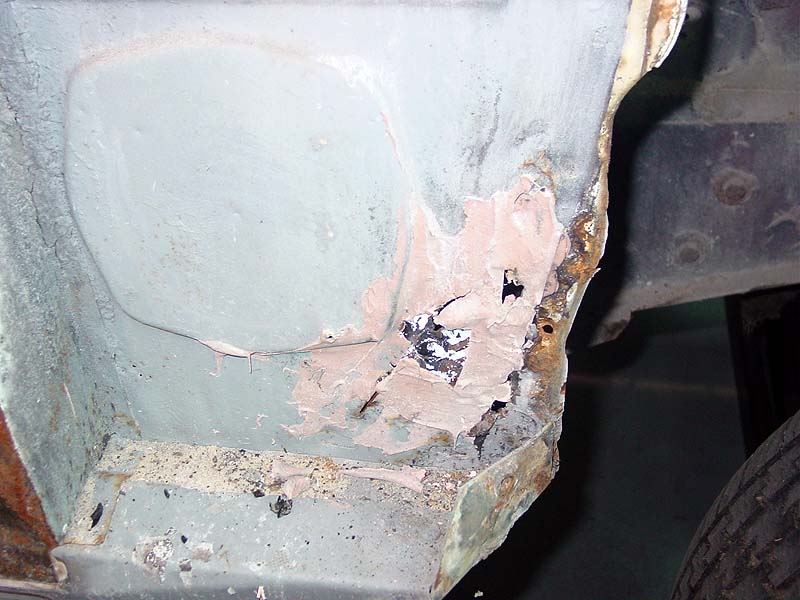
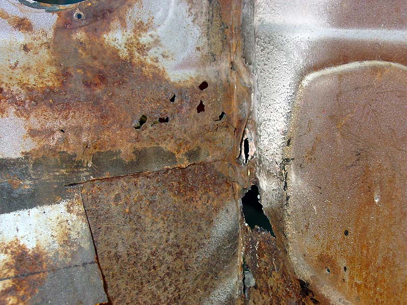
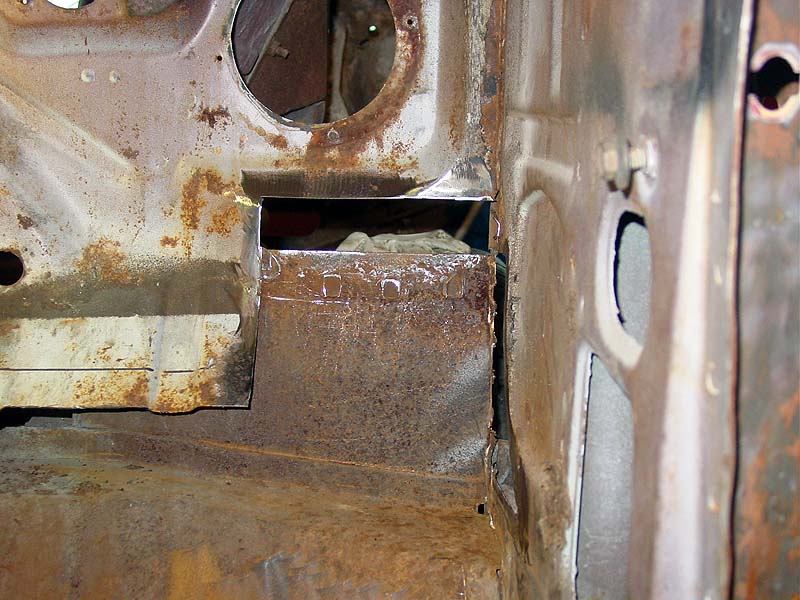
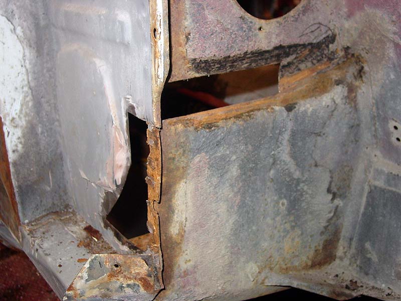
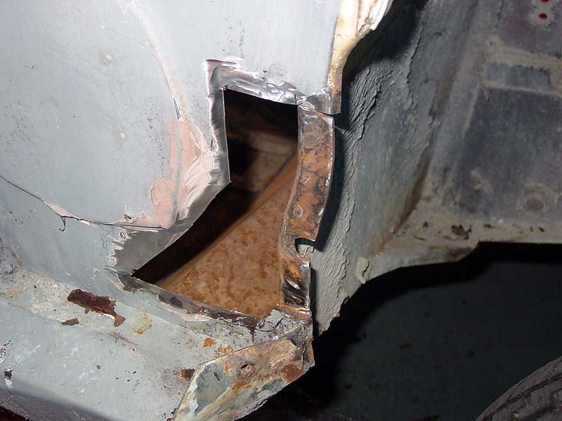
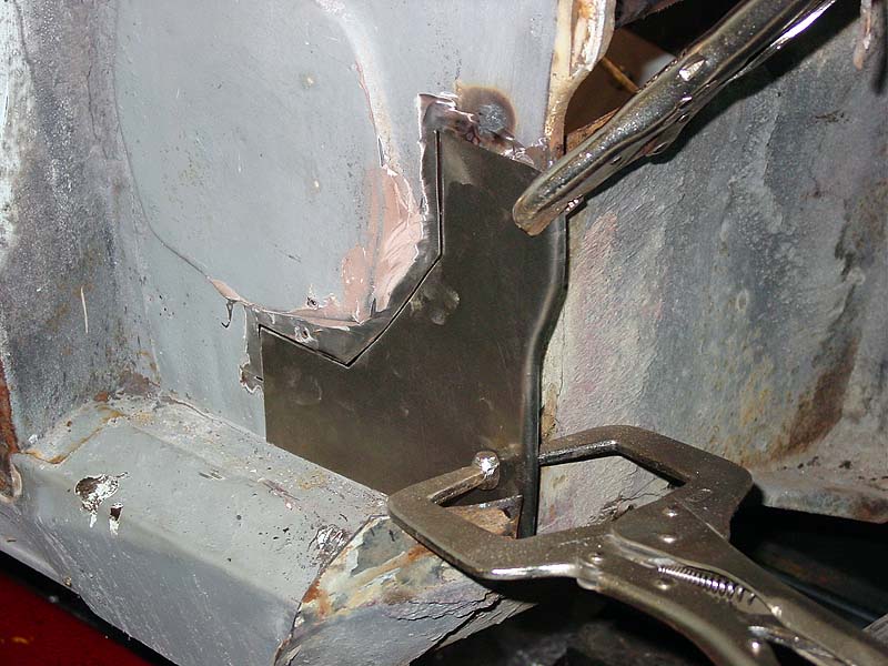
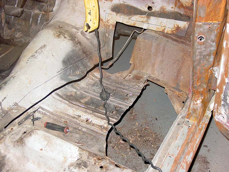
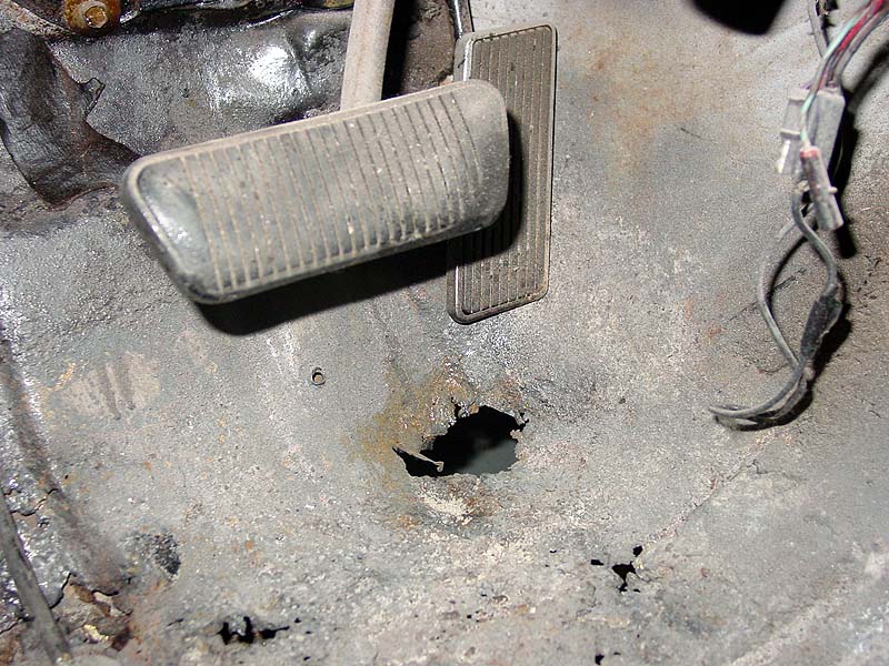
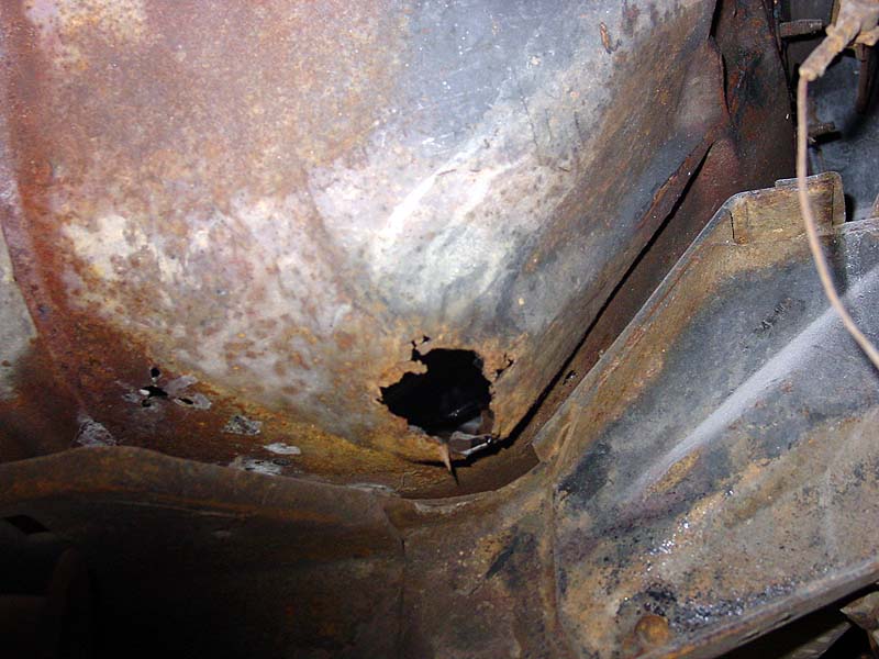
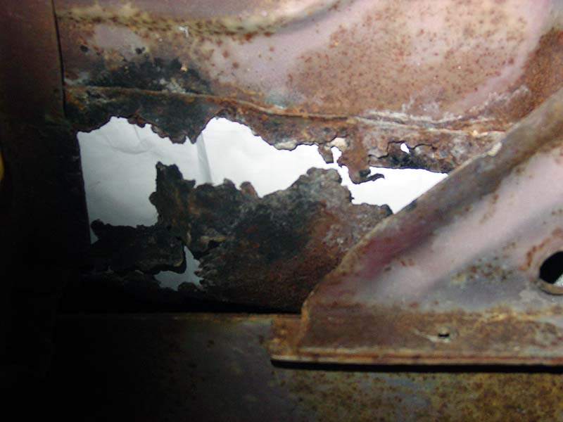
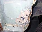
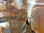
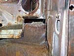
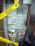
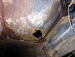
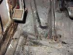
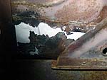
7/15/07 - Demolition Continues
Seems as though someone thought it would be a good idea to just grab the
can of Bondo and quickly fix a hole behind the kick panel. You can
see how great that worked. Also noted some pinholes in the firewall,
and after hitting with a screwdriver, there were holes everywhere.
Only one solution here - cut out the material, fabricate new pieces and
weld in. This is still in process.

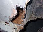
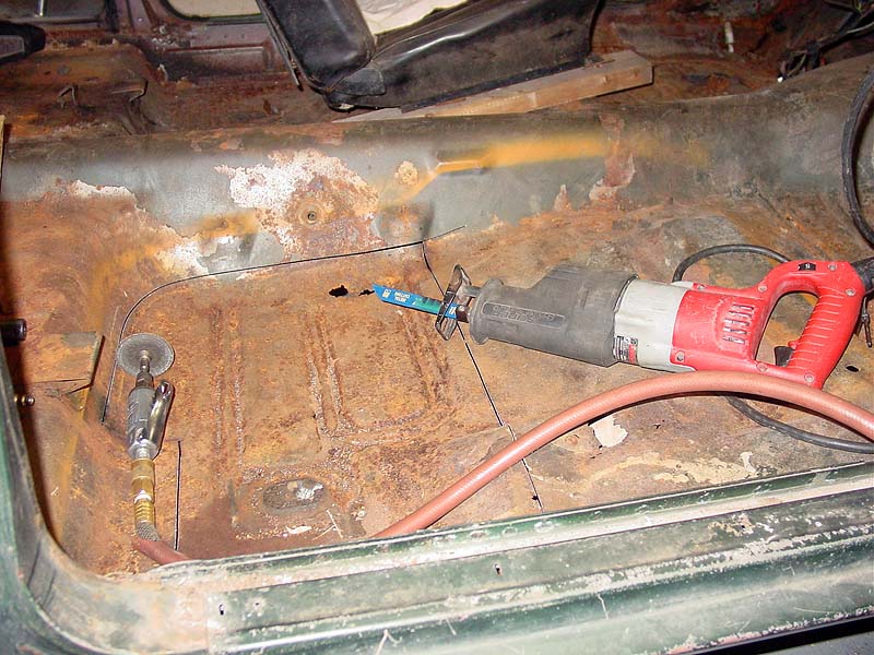
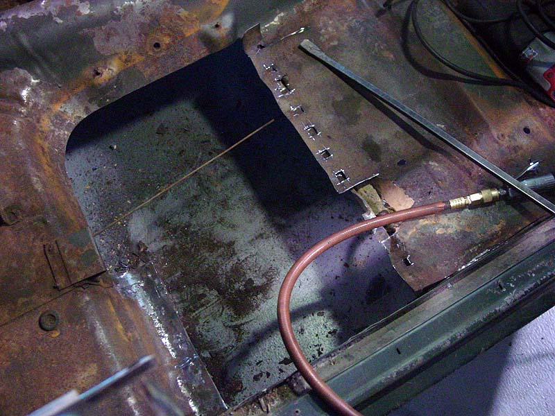
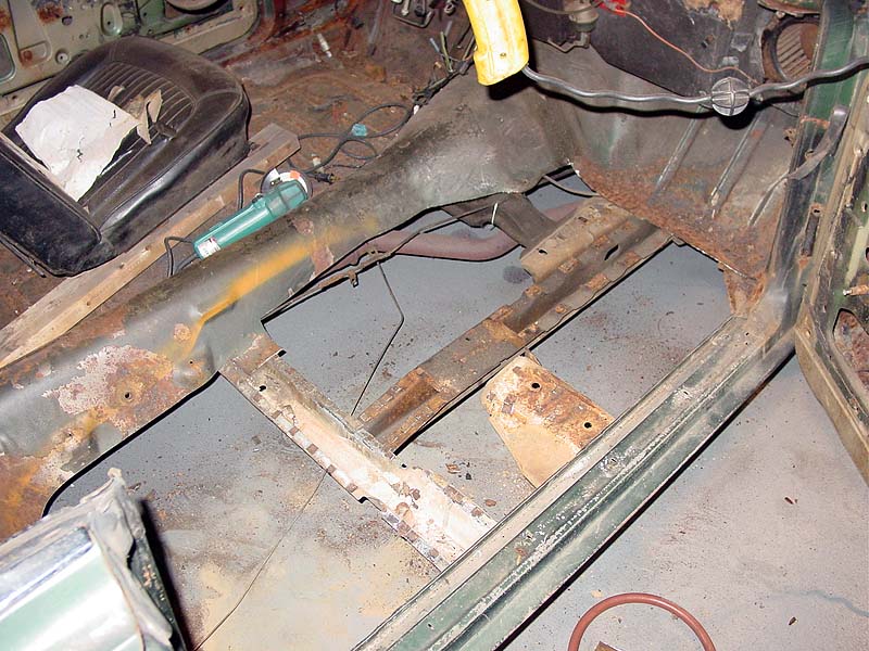
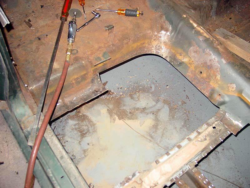
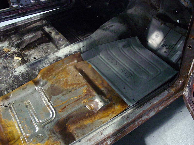
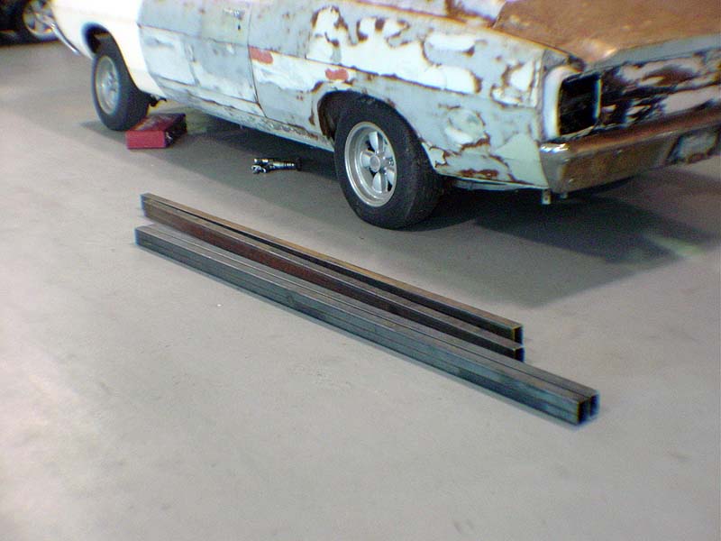
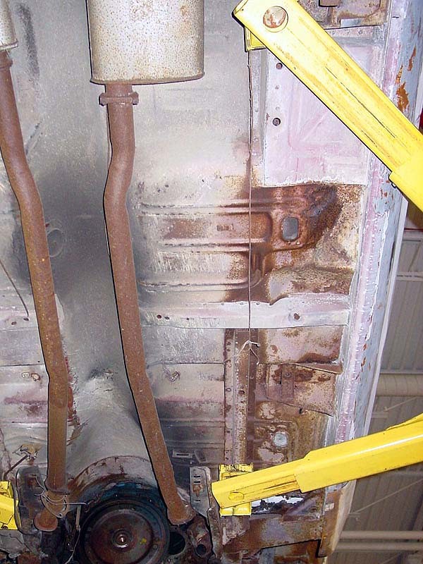
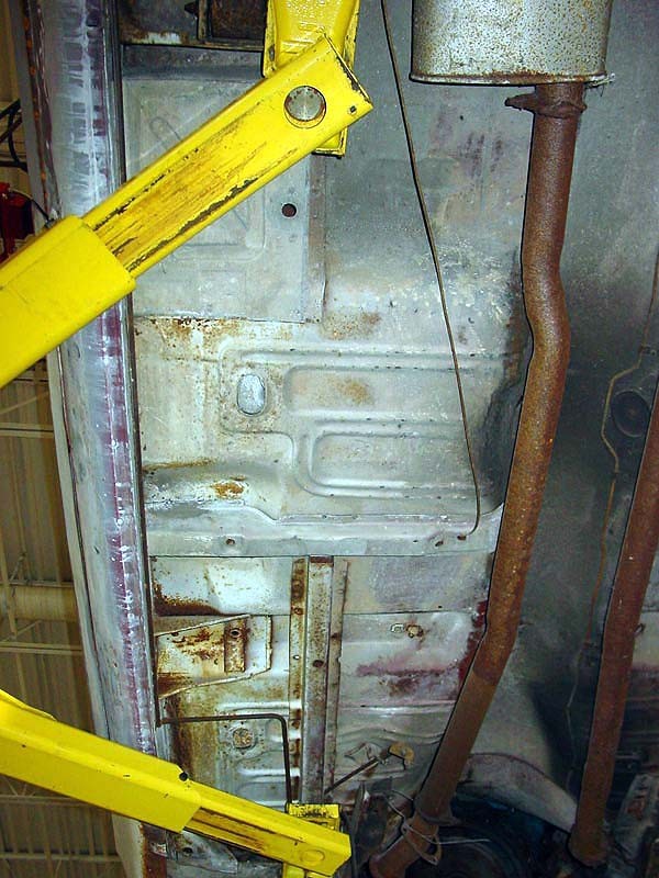
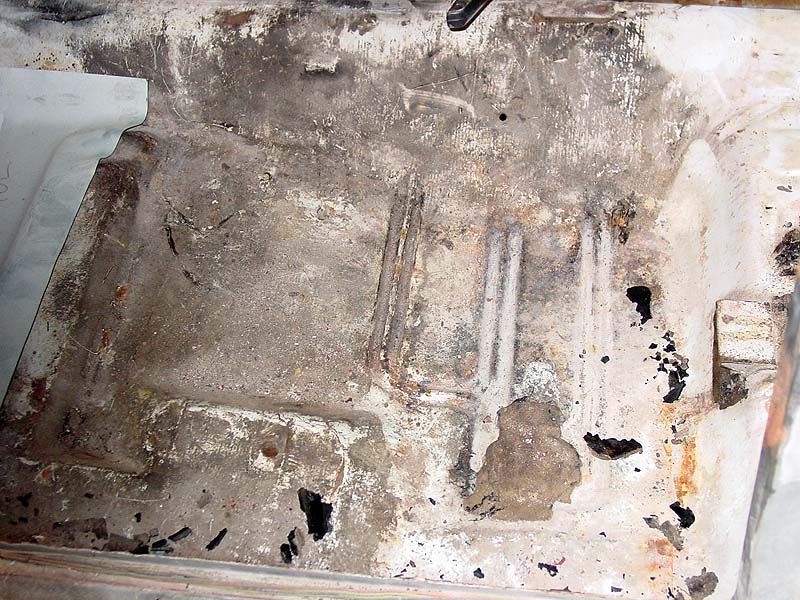
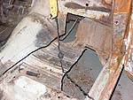
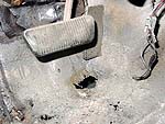
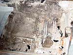
6/29/07 - Floors be gone:
The official construction of the cars has started. The floor
demolition was commenced, and it did not take long before the passengers
side was long gone. The surrounding structures of the rockers and
torque box were in excellent shape which makes this job a pleasant one.
Most of the time a rusted torque box comes as a surprise once the floors
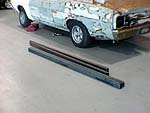
are cut out. As you can see, the stock has also been purchased to
make full length subframe connectors. Material used is mild steel
2"x3"x0.125". We are now in the process of determining how to
integrate the subframe connectors with the front Mustang Suspension and
the rear IRS.
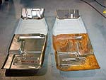
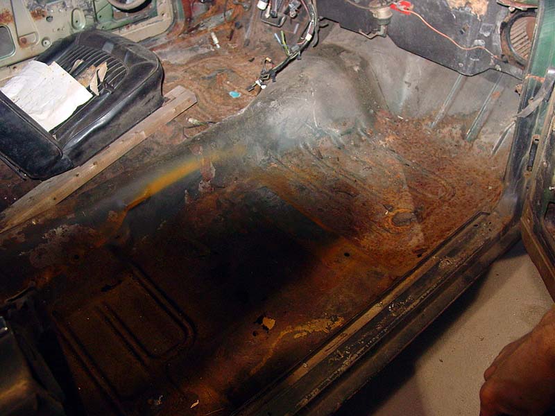
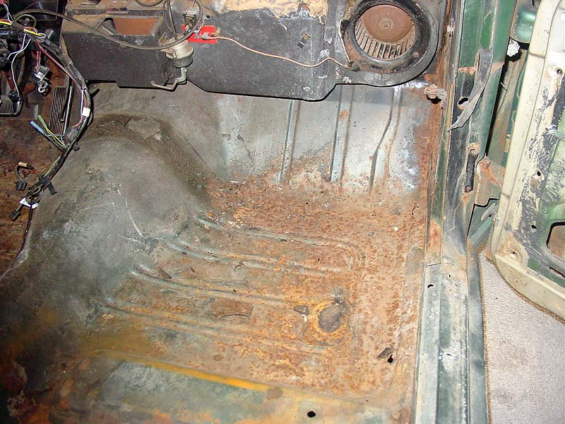
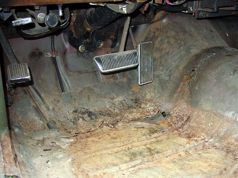
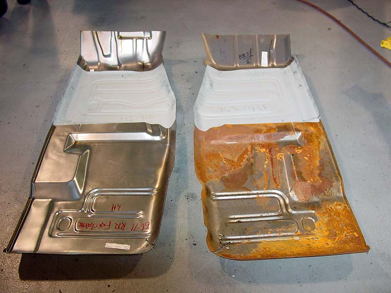
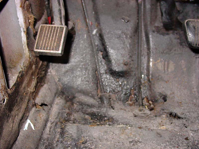
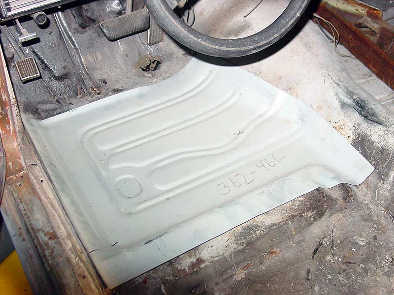
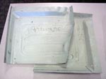
In the beginning:
Rusted floors are best when they come in pairs. Texas Torino also
requires floor surgery. For as old as the car is, the floors are in
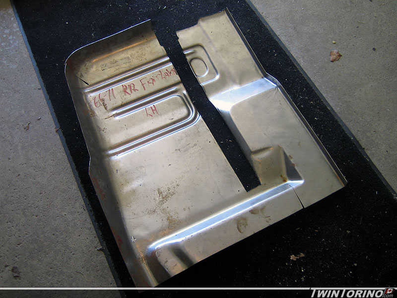
good condition considering. Replacement panels were bought off eBay at a lower cost
including 2 front floor pans and the right rear. The search is on
for toe pans and then the process can begin. After looking the
floors over, the car really only needs the toe pans and can get by with a
patch piece at the front of the floor pans. This way the purchased
pans be used on the Georgia Torino where they are really needed.
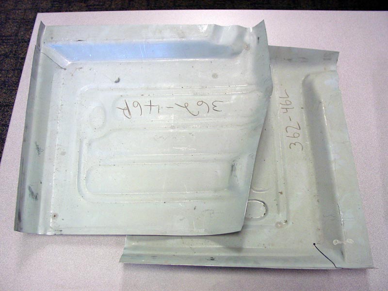
Overall Floor Structure

Driver's Side
Passenger's Side
Replacement
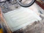
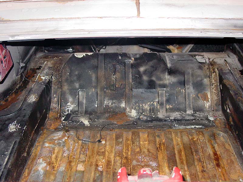
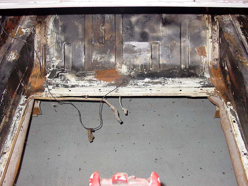
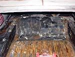
Trunk Floor
This one is somewhat Torino unique in that most of the trunk floor is
actually the fuel tank as can be seen below. Trunk is in excellent
shape and needs nothing - only requires stripping and refinishing.
 |